Generating Surface Data for Computerized
Flight Simulations
Lockheed Martin meets tight deadline for the 3D scanning and point-cloud processing of a 1950s fighter jet.
In 2005, the Lockheed Martin Missiles & Fire Control unit became intrigued by the aerodynamics of a 50-year-old Swedish-built fighter jet, the Saab A-35 Draken. LM M&FC aerodynamics experts needed a very accurate data map of the aircraft that could be imported into engineering analysis tools to obtain real aerodynamic performance.
Complete, accurate surface data of the entire aircraft plus high-resolution scans of weapons and gun bays were required. Lockheed Martin came to Exact Metrology for scanning capabilities that would generate surface data to be fed into computerized flight simulations.
The data was needed to ensure that weapons delivery systems would survive in 21st-century combat environments. Aerospace contractors such as Lockheed Martin continually search for ways to mitigate the high costs of testing. One solution is using a commercial activity instead of a military test facility—and digital rather than physical means.
The Challenge
- Capturing the 3D shape of a full-size airplane of 50 feet long with a 31-foot wingspan
- Quickly deliver NURBS surfaces to simulation software
- Process data obtained from high- and low-resolution scanners
Three big scanning-and-digitizing challenges were faced:
- Speed: Lockheed Martin was in a hurry because it faced 90 days of nonstop data crunching in flight simulations. Initial surfaces data was needed in a week and Exact Metrology got it to them.
- Size of the model: The Draken was a huge model to digitize. The aircraft is over 50 feet long with a 31-foot wingspan and a rudder standing nearly 14 feet high. To minimize the file size, two types of scanners were used: a high-resolution scanner (VIVID 910 from Konica-Minolta) for highly detailed areas, and a low resolution (and faster) scanner (Cyra2500 from Leica) for flat areas.
- Flexibility: Exact Metrology needed a software solution that would process data obtained from both high- and low-resolution scanners.
To meet these challenges, Exact Metrology turned to PolyWorks®, the leading point cloud processing software solution from InnovMetric Software.
The Solution
Choosing the right crew on the field
Exact Metrology got the job because of its unique experience in long-range and short-range scanning. It also helped that Exact Metrology could react right away.
It got the Lockheed Martin call one week before Thanksgiving (2005). Matt Cappel, Manager at Exact Metrology, and a scanner operator were on a plane to Los Angeles three days later. The scanning was completed in two days and they were home for Thanksgiving. The scanning was done at Inyokern, in California’s Mojave Desert. Six of the remaining Drakens are refurbished and flown there.
For the Draken project, Exact Metrology needed to speedily process several gigabytes of point-cloud data in wildly differing resolutions—as much as 10,000x or five orders of magnitude—into a single CAD model. In the high-resolution work, Exact Metrology gathered 266 point clouds averaging 250,000 points apiece. This was close-in, short-range work capturing images about two square feet, using a Minolta VIVID 910 scanner.
The low-resolution scans were done with a Cyra2500 from Leica Geosystems. For these scans, the technicians gathered about 20 million points. “This was sufficiently precise for even the smallest aerodynamic shapes but not so high in resolution to capture unneeded data such as rivet heads and hinge points,” Cappel said. “The low-resolution work was more like a surveying application for us.”
After all the scanning and digitizing—about 250 high- and low-resolution scans aggregating 4.6 gigabytes of data—Exact Metrology’s final deliverable to Lockheed Martin was a relatively small 200 megabytes (MB), uncompressed file.
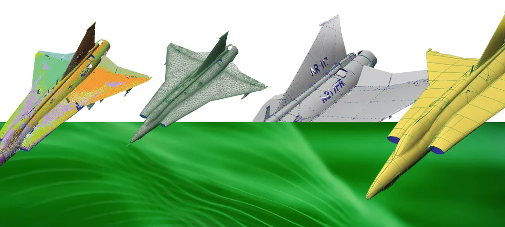
Scan alignment
The PolyWorks|IMAlign™ module was used to align the 260 scans into a single model. The PolyWorks alignment technique does not require the use of targets or markers on the part. Instead, it uses the geometrical shape of the scans themselves to align them to each other. “Not having to use targets on the plane dramatically improved the scanning process,” declared Cappel.
Polygonal model
After the scans were aligned, the resulting point cloud model was transformed in the PolyWorks|IMMerge™ module into a polygonal model in the Stereolithography Tessellation Language (STL) format. PolyWorks creates a polygonal mesh (triangles) adapted to the surface curvature, preserving high resolution across edges and fillets while creating larger triangles in flat areas. Some simulation software packages can process STL files, however the system used by Lockheed Martin M&FC did not support them. A CAD-usable file was needed.
Constructing a curve network
To create a CAD-usable model, PolyWorks computes a mathematical representation of the surfaces called NURBS (non-uniform rational B-splines) on the polygonal model. Prior to computing the NURBS surfaces, a curve network is built on the polygonal model, to determine where the surfaces are to be fitted. PolyWorks provides both automatic and manual tools to create the curve network. Feature curves can be extracted in one click of the mouse using PolyWorks’ extracting algorithms. And the curve network can be refined manually with techniques that require only a couple of clicks by the user.
NURBS surfaces
NURBS surfaces were then automatically fitted on the curve network. These surfaces were exported as IGES or STEP files to Lockheed Martin’s analysis system. The final deliverables met Lockheed Martin’s requirements in terms of accuracy, file size, and number of patches.
PolyWorks generates NURBS surfaces that truly work in CAD.
Three factors contributed heavily to the quality of the NURBS surfaces:
- The high quality of PolyWorks' polygonal model underlying the NURBS surfaces.
- The ability to determine critical feature curves while constructing the curve network and constraining the NURBS surface creation to these critical curves.
- The possibility of using T-junctions while creating the curve network, which ensures a more logical patch layout.
The Benefits
From scanning to final deliverables, Exact Metrology took two and a half weeks to capture, edit, and format the huge amount of Saab A-35 scanned data to Lockheed Martin’s requirements. “For a job in the multiple gigabyte range, this is a very fast turnaround,” said Cappel. It is estimated that there was a savings of 67% to 80% in data acquisition time, and 50% in data processing time.
“All the Lockheed people that we worked with told us they were absolutely thrilled with the quality and comprehensiveness of the data. There have been no glitches and no restarts, which can destroy simulation schedules. InnovMetric’s Application Specialists were a great help to us. They were like having an extra technical employee on our staff, getting us over the rough spots.” Matt Cappel, Manager at Exact Metrology
Quantifiable benefits:
- The entire aircraft, every external surface, was scanned and digitized in two days by just two people. Other methods would have taken two to four times longer, so there was a 67% to 80% savings in data acquisition time.
- Only PolyWorks could be relied on to accurately handle 4 gigabytes of data. Otherwise, the file would have to be split into several pieces, requiring additional merging steps and data assembly, doubling and possibly tripling the processing time.
- Competing packages were nowhere near as fast, and time was of the essence. PolyWorks saved an estimated two weeks over less efficient software.
- Dramatic cost savings in terms of computer-based simulation instead of physical testing in wind tunnels.
The Future
As Lockheed Martin explained it to Exact Metrology, the Saab A-35 project intent was to gain a better understanding of the aerodynamics of a potential test aircraft from a commercial company, and that was accomplished.
The aerodynamics of the Draken was revolutionary for its time and is still impressive today, half a century later. The Draken was designed:
- For short takeoffs and landings at small airfields close to battle zones.
- For an optimized combination of high-speed and low-speed performance.
- To be rearmed between missions in minutes.
- To be bolted together so the aircraft’s four segments could be replaced, sent off for service, or upgraded.
Thanks to Exact Metrology and InnovMetric, Lockheed Martin now has all the aerodynamic details in its flight-simulation systems—quickly and at very low cost.